
15043460
Description
Flashcards by Brittany O'Brien, updated more than 1 year ago

|
|
Created by Brittany O'Brien
over 6 years ago
|
|
| Question | Answer |
| Hatch Equipment Module | |
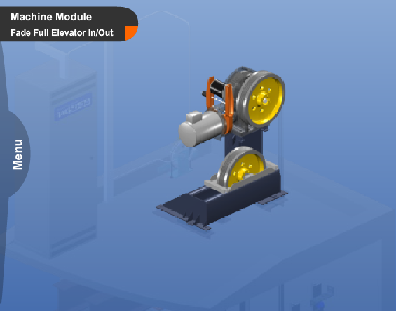
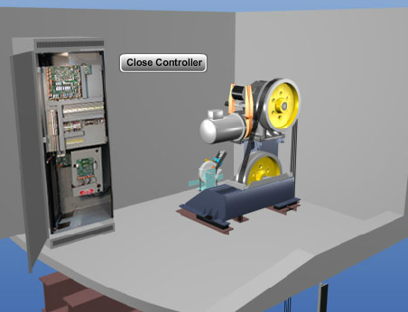
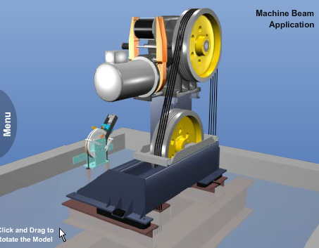
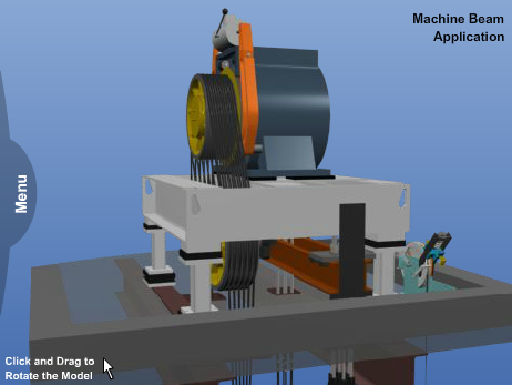
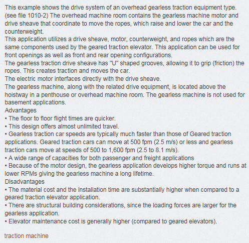
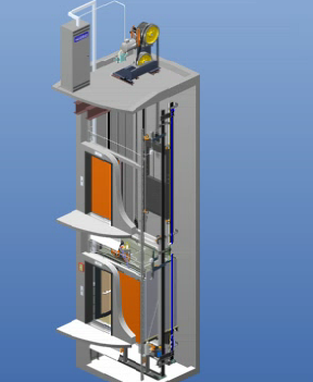
| A traction machine is used on all traction elevator equipment types. A standard traction machine consists of a motor, drive sheave, brake and machine bed plate. The traction machine motor turns the drive sheave shaft to turn the drive sheave. As the sheave turns the hoist ropes pass over the drive sheave and pull the car through the hoistway. This diagram shows a traction machine located in an overhead machine room. traction machine Sheave motor brake | |
| Governor Module | |
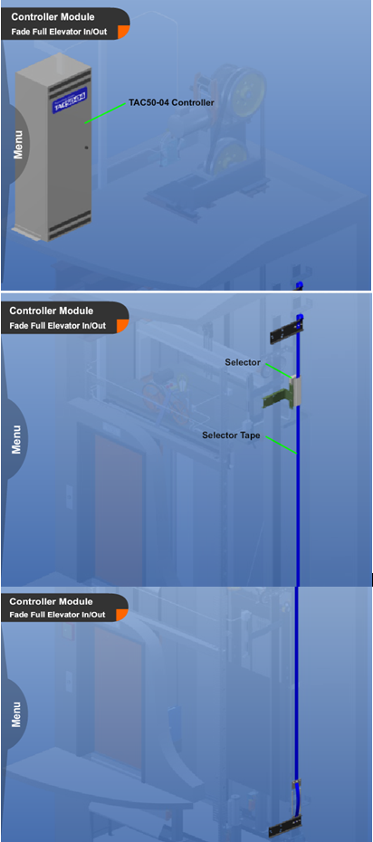
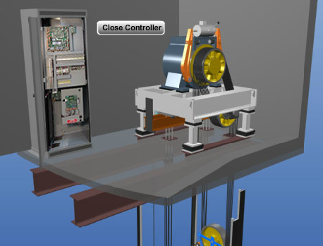
| Controller / Selector Module | |
| Entrance Module | Entrance: The framework for the opening is called the entrance and is set into the hoistway wall. The entrance provides safe access to the elevator car. It protects the passenger from entering the hoistway unless an elevator has arrived at the landing. It also protects the passenger who is riding in the car, in conjunction with the car door, by preventing the passenger from disembarking until the elevator has arrived safely at a landing. The entrance assembly must be fire rated as a function of the hoistway construction type. There are typically three types of hoistway construction types that require specific entrance designs: block, drywall & steel stud, drywall & wood stud. The entrances are “labeled” with a fire rating and this label is inspected at installation completion to be sure that the correct entrance type was installed. traction entrances door |
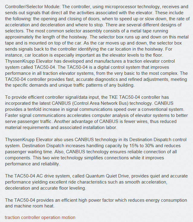
| Cab Module | Cab Module: The cab module may be either a passenger or freight type. The cab module is made up of a number of assemblies: enclosure; platform, car frame; car door or gate. The cab enclosure is the part of the elevator that people or freight ride in. A freight cab is typically constructed from a series of formed sheet steel wall panels. A passenger cab has many options for the finished interior enclosure materials: such as stainless steel, bronze, cold rolled steel and plastic laminate. (see file 1004-13) Both the freight and passenger cab sizes are designed to size standards provided by the A17.1 Safety Code for Elevators & Escalators. For passenger elevators a maximum inside net platform area is provided in relationship to capacity. For instance, a 2,500# capacity would be a maximum of 29.1 square feet. For freight elevators the size is governed by the type of freight to be hauled and a design formula. traction cab finishes Architectural |
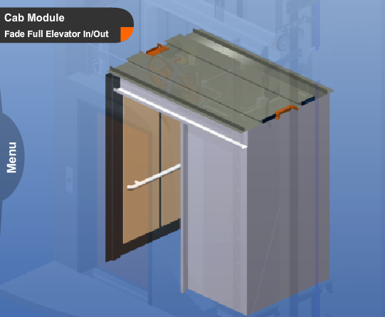
| Door Equipment Module | Door Equipment Module: The door equipment module consists of numerous assemblies. In its simplest form, this equipment opens, closes, and locks the cab and hoistway doors. The major assemblies consist of the door operator, header, tracks, hanger rollers, interlock, clutch, and closures. traction Doors entrances |
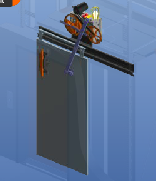
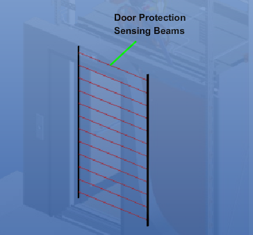
| Door Protection Module | Door Protection Module: This module contains assemblies that keep the doors from attempting to close on passengers when they enter or leave the elevator. The three major assemblies within this module are as follows: • Power supply: sends power to the transmitter and receiver. The power supply is usually mounted on the top of the car. • Transmitter: transmits infrared "beams" across the door opening. Any obstruction within the door opening will break this beam. • Receiver: receives the infrared "beams" from the transmitter. These assemblies are located on the car. traction Safety door cab |
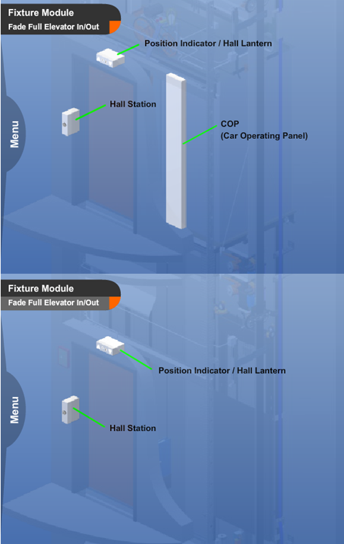
| Fixture Module | Fixture Module: The car operating panel and hall push buttons allow the elevator user to give commands to the elevator. The position indicator, in turn, tells the user the location of the elevator. The directional lantern indicates which direction the elevator will be traveling on the next start. The fixture module includes the hall push button stations, car operating panel, position indicators and directional lanterns. traction Signals Fixtures |
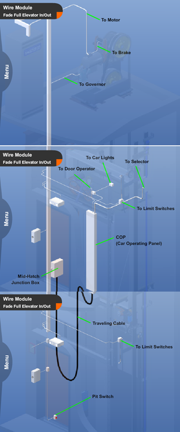
| Wiring Package Module | Wire Package Module: The wiring package module contains material used to wire the complete elevator package. The wiring package consists of standard electrical components such as duct, junction boxes, conduit, and fittings. The wiring package also consists of wire that is unique to elevators. A traveling cable is an electrical "cable" consisting of numerous conductors that electrically connect the moving car to the elevator controller in the machine room. The traveling cable is an “engineered” cable designed and manufactured to prevent twisting as the elevator moves through the hoistway. The cable is also designed to be strong enough to withstand the constant movement. The cable is composed of electrical conductors to allow control signals, electricity for lighting, fans and utility outlets. The cable also includes shielded pairs for communication devices such as telephones. traction controller wiring |
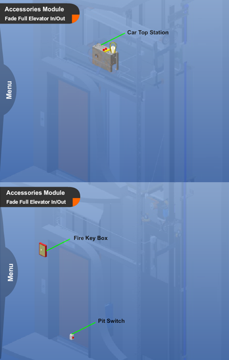
| Accessories Module | Accessories Module:This module contains a number of individual components that do not necessarily have a relationship with other modules: Pit Switch: A safety device used to disable the car before entering the pit. Car Top Station: A device, located on top of the car, used by maintenance personnel to control the car movement. Fire Key Box: Fire key box contains the key to activate phase I fire service (used by firefighters or rescue personnel). It is typically mounted in the hall, next to the opening at the egress level. traction hoistway |
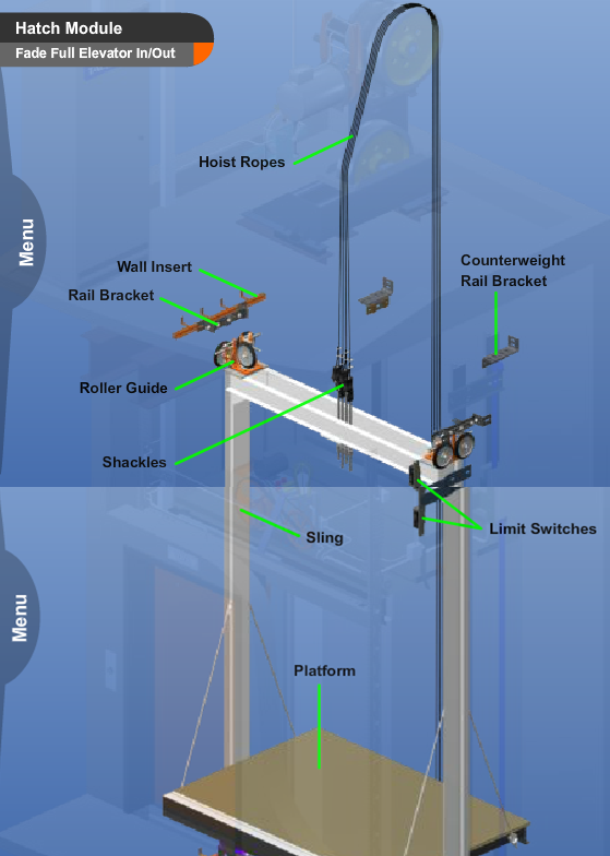
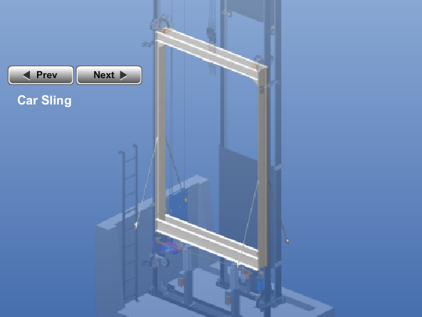
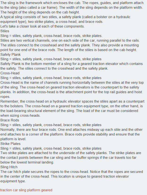
| Car Sling - Geared | |
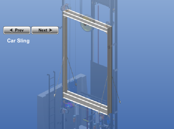
| Car Sling - Gearless | |
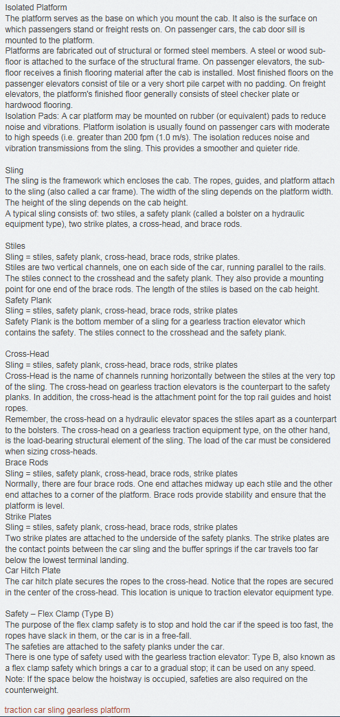
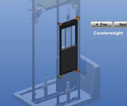
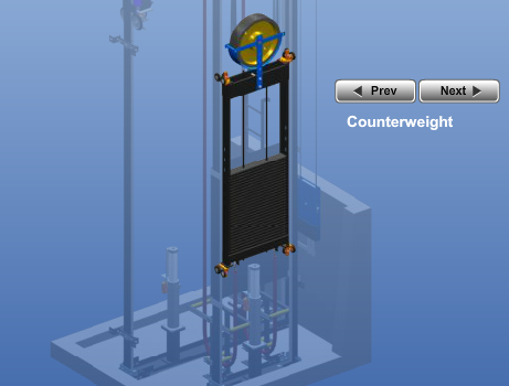
| Counterweights - Geared | The counterweights consist of individual flat plates of steel. The number of plates in the stack depends on the amount of weight required. The counterweights are secured within the counterweight frame by rods that run through the weights themselves. This design prevents the plates from becoming loose and falling out. Counterweight Hitch Plate Counterweight hitch plate is the attachment point for the other end of the ropes. The ropes are attached to the counterweight frame by a hitch plate similar to the car hitch plate. The car hangs on one end of the ropes and the counterweights hang on the other end. Counterweight Guard A Counterweight guard is located in the pit area. It is designed to protect individuals working in the pit from being struck by the counterweights as they come down. traction counterweight geared |
| Counterweights - Gearless | The counterweights consist of individual flat plates of steel. The number of plates in the stack depends on the amount of weight required. The counterweights are secured within the counterweight frame by rods that run through the weights themselves. This design prevents the plates from becoming loose and falling out. Counterweight Hitch Plate The attachment point for the counterweight end of the ropes. The ropes are attached to the counterweight frame by a hitch plate similar to the car hitch plate. The car hangs on one end of the ropes and the counterweights hang on the other end. Counterweight Guard A Counterweight guard is located in the pit area. It is designed to protect individuals working in the pit from being struck by the counterweights as they come down. The counterweight guard can not be used when rope compensation is used. traction counterweight gearless |
| Geared Traction Controller | |
| Gearless Traction Controller | |
| Geared Machine | |
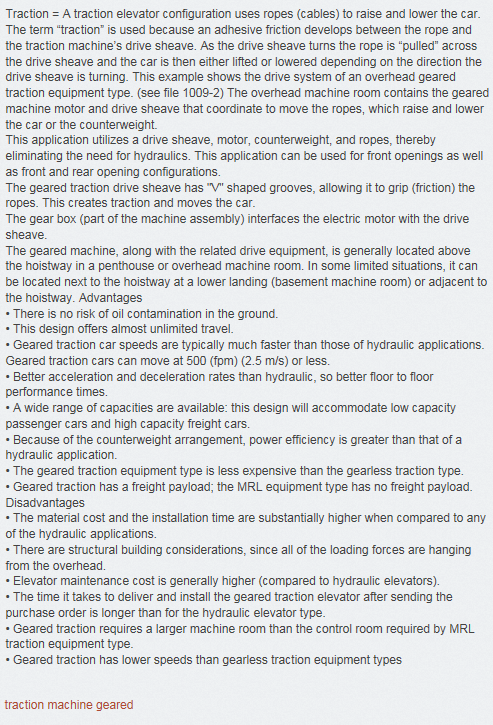
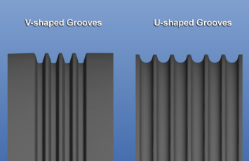
| Geared Traction Drive Sheave | The geared traction drive sheave has "V" shaped grooves, allowing it to grip the ropes. This creates traction and moves the car. Geared traction drive sheaves may have 3 to 9 grooves. traction machine gearless |
| Gearless Traction Machine | |
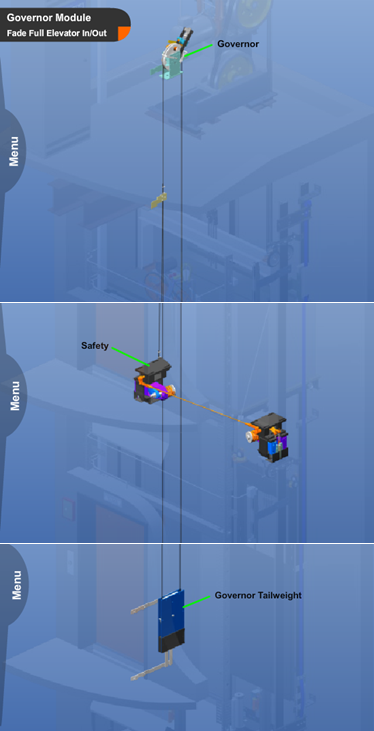
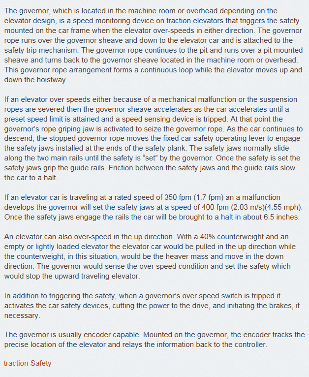
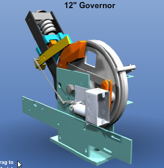
| Governor | The governor is a mechanical speed control mechanism. The governor monitors the speed of the car in the down direction by using one rope. If the car travels too fast in the down direction, the governor is tripped and a set of safeties are engaged to stop the car. traction Safety |
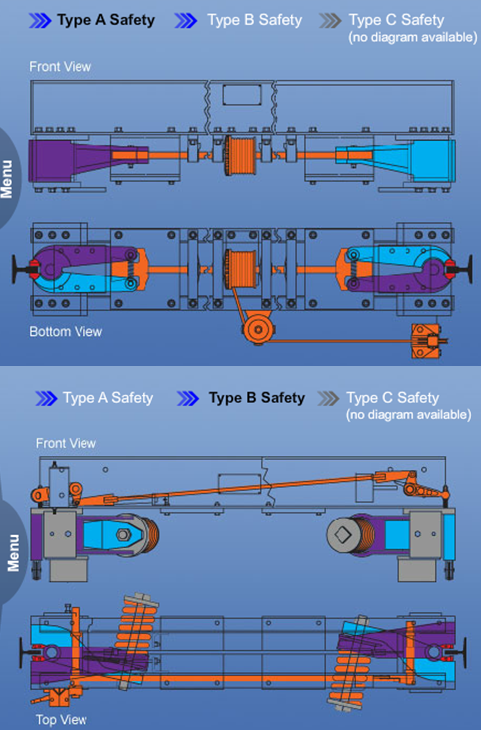
| Safeties | Safeties The purpose of the safeties is to stop and hold the car if the speed is too fast, the ropes have slack in them, or the car is in a free-fall. The safeties are attached to the safety planks under the car. There are three types of safeties: Type A, B, and C. Type A Brings car to an immediate stop. Can only be used on speeds under 151 fpm (0.77 m/s). Type A safeties are the least expensive. Type B Brings car to a gradual stop. Can be used on any speed. Type C Brings car to a gradual stop. Can only be used on speeds under 501 fpm (2.55 m/s). This is an older design that is rarely used. Note: If the space below the hoistway is occupied, safeties are also required on the counterweight. traction Safety governor |
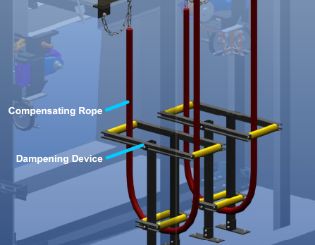
| Rope Compensation | When the hoist ropes reach a certain length, their weight can affect the balance of the car. A compensating rope is used to counter-balance the weight of the hoist ropes. This creates an equal distribution of the load on the drive sheave and motor, regardless of the car's position in the hoistway. One end of the compensating rope is fastened to the bottom of the sling and the other end is attached to the bottom of the counterweight frame. Compensating ropes are generally used when the travel is 100 Feet or greater. traction roping |
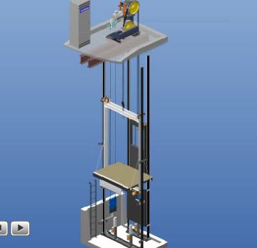
| Geared Traction Moving | |
| Geared Traction Moving in Hoistway |
0 comments
Want to create your own Flashcards for free with GoConqr? Learn more.