
36938858
Description
Programming UART ports
- Review
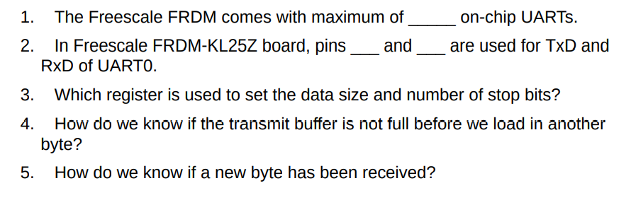
Questions
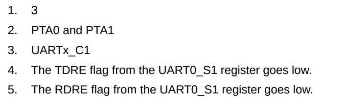
- Answers
- Answers
- Definition: UART serial port registers
of Freescale ARM KL25Z are configured
in order to transmit and receive data
serially.
- Freescale ARM chips come with up to 3 on chip UART ports (UART0 - UART2).
- UART0
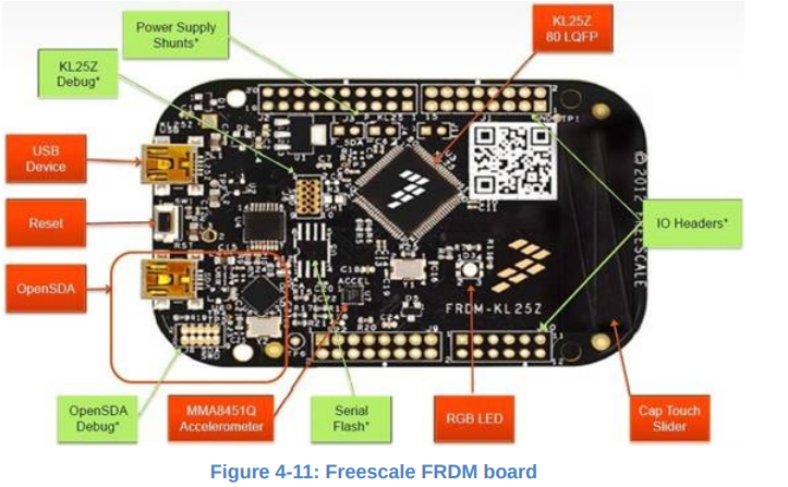
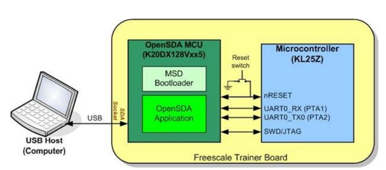
- Ex. In the Freescale FRDM, UART0 port is connected to the OpenSDA (Open Serial Debug Adaptor),
which is connected to a USB connector.
- When the USB cable connects the PC to the FRDM board, the device driver at the host PC establishes
a virtual connection between the PC (as COM port) and the UART0 of the KL25Z device (as UART0).
- When the USB cable connects the PC to the FRDM board, the device driver at the host PC establishes
a virtual connection between the PC (as COM port) and the UART0 of the KL25Z device (as UART0).
- Baud clock and
oversampling
- How is it calculated?
- Formula
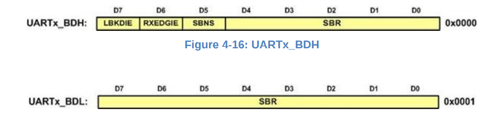
- SBR is the concatenation UART0_BDH:UART0_BDL (13
bits).
- OSR (oversampling rate) is the D4-D0 of UART0_C4.
- OBS: if OSR < 7, BOTHEDGE of UART0_C5 must be set.
- OBS: if OSR < 7, BOTHEDGE of UART0_C5 must be set.
- SBR is the concatenation UART0_BDH:UART0_BDL (13
bits).
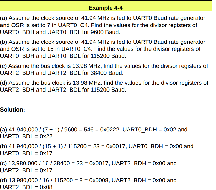
- Solved
Examples
- Formula
- Related registers
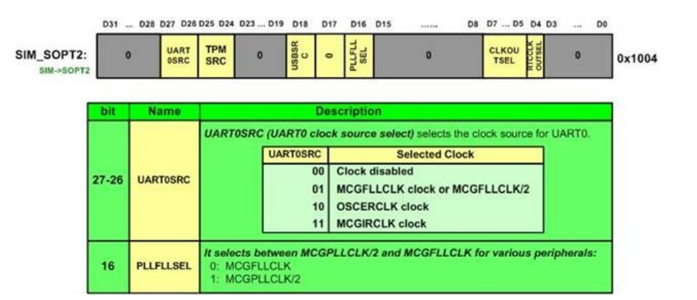
- SIM_SOPT2
register
- Register used to configure the source
of the Baud rate generator clock for
UART0. It selects from the output of
FLL, PLL, the external oscillator, or
the internal oscillator.
- Register used to configure the source
of the Baud rate generator clock for
UART0. It selects from the output of
FLL, PLL, the external oscillator, or
the internal oscillator.
- UARTx_BDH and
UARTx_BDL
- UARTx_C4
- SIM_SOPT2
register
- Bald rate error
- How is it calculated?
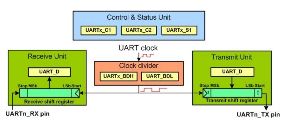
- Control and Status Unit
- Registers
- UARTx_C1
- 8-bit register that is used to select the data frame size
(choose bit M for 8-bit or 9-bit frame size), if there will be
parity bit, and what the type of parity bit is, among other
functions.
- 8-bit register that is used to select the data frame size
(choose bit M for 8-bit or 9-bit frame size), if there will be
parity bit, and what the type of parity bit is, among other
functions.
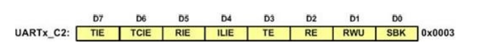
- UARTx_C2
- 8-bit register used to configure if transmit
(TE)/receive (RE) is enabled or not, and the rest of
the bits are used for interrupt driven serial
communication.
- 8-bit register used to configure if transmit
(TE)/receive (RE) is enabled or not, and the rest of
the bits are used for interrupt driven serial
communication.
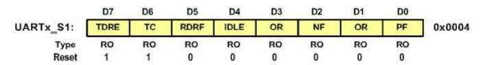
- UARTx_S1
- It is the most important UART status register. It
monitors the arrival of data among other
things. We monitor (poll) TC flag that all the
bits of last byte are transmitted. We monitor
(poll) the RDRF flag to see if a byte of data is
received. The TDRE flag indicates that the data
register is empty and ready to accept another
byte.
- UARTx_C1
- Registers
- Receive/Transmit unit
- Register
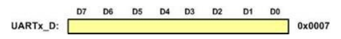
- USART_D
- It is the USART Data
Register, where data is
stored before transmitting
and after receiving.
- Advanced: There are actually 2
separate registers with the same
address and the same name, for
transmitting and receiving data.
Writing to the memory address
leads to write to the transmit
register and reading from the
memory address return the
received data.
- It is the USART Data
Register, where data is
stored before transmitting
and after receiving.
- USART_D
- Register
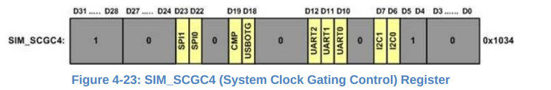
- Enabling clock
- To enable clock for peripheral UART0, set the bit D10 of register SIM_SCGC4
- To enable clock for peripheral UART0, set the bit D10 of register SIM_SCGC4
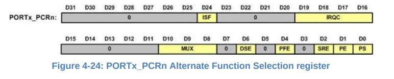
- I/O pins used for UART
- It is necessary to set up
I/O pins for the
alternate functions of
TxD and RxD signals
- It is necessary to set up
I/O pins for the
alternate functions of
TxD and RxD signals
- Ex. In the Freescale FRDM, UART0 port is connected to the OpenSDA (Open Serial Debug Adaptor),
which is connected to a USB connector.
- UART0
- Freescale ARM chips come with up to 3 on chip UART ports (UART0 - UART2).
- OpenSDA
- Main functions:
- 1. Programming (downloading) using OpenSDA Programming software;
- 2. Debugging using JTAG;
- 3. Use as a virtual COM port;
- 3. Use as a virtual COM port;
- 2. Debugging using JTAG;
- 1. Programming (downloading) using OpenSDA Programming software;
- Main functions:
- UARTx
- Groups of registers in UART peripherals
- Configuration Registers
- Must be initialized before using the
UART peripheral. This set some
parameters for communication
including: baud rate, word length,
stop bit, serial interrupts (if needed).
- UARTx_BDH (Baud Rate High)
- UARTx_BDL (Baud Rate Low)
- UARTx_C1 (control 1)
- UARTx_C2 (control 2)
- UARTx_C2 (control 2)
- UARTx_C1 (control 1)
- UARTx_BDL (Baud Rate Low)
- Must be initialized before using the
UART peripheral. This set some
parameters for communication
including: baud rate, word length,
stop bit, serial interrupts (if needed).
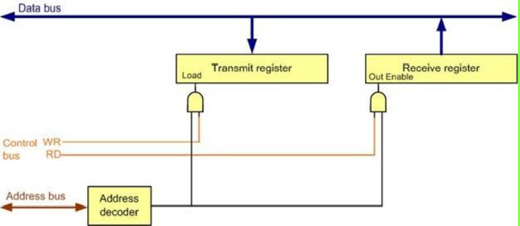
- Transmit and receive register
- To send data, we simply
write to the transmit
register (UART_D). The
received data is stored in
the receive register
(UART_D). The data is
transmitted through serial
transmit pin (UARTx_TX) and
received through serial
receive pin (UARTx_RX).
- UART_D (transmit/receive register)
- To send data, we simply
write to the transmit
register (UART_D). The
received data is stored in
the receive register
(UART_D). The data is
transmitted through serial
transmit pin (UARTx_TX) and
received through serial
receive pin (UARTx_RX).
- Status Register
- Contains flags that show the state
of sending and receiving data,
including: existence of new
received data, error in received
data, sending unit ready for new
data, etc.
- UARTx_S1 (status register)
- Contains flags that show the state
of sending and receiving data,
including: existence of new
received data, error in received
data, sending unit ready for new
data, etc.
- Configuration Registers
- Clock
- Transmitter
- Operates on the
clock that runs at
the BAUD RATE.
- 1 clock, 1 bit transmitted
- 1 clock, 1 bit transmitted
- Operates on the
clock that runs at
the BAUD RATE.
- Receiver
- Detects the falling edge of the starting bit
- Oversampling
- Runs in a faster clock than baud rate.
- Runs in a faster clock than baud rate.
- Oversampling
- Detects the falling edge of the starting bit
- Transmitter
- Groups of registers in UART peripherals
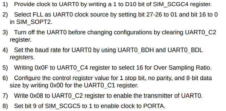
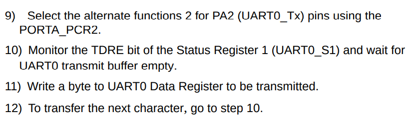
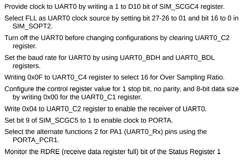
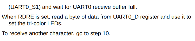
- Useful steps for LAB
- Transmitting data
- Receiving Data
- Transmitting data
Media attachments
0 comments
Want to create your own Mind Maps for free with GoConqr? Learn more.